SiO2 Wafers - Thermal Oxide Silicon Wafers Wet & Dry
Wet and Dry Thermal Oxide
It can be hard to find a quality thermal oxide supplier, especially if you're looking for a specific type of wet or dry thermal oxide and have questions.
A postdoc requested a quote for the following:
I would like to get for: Deposit Thermal Oxide on a 76mm silicon wafer with 2850 Angstroms Oxide layer. Package of 25 Quantity.
Actually, I need your recommendation on selecting the right wafer. I am currently growing MoS2 with the CVD method. Later I transfer them to other surfaces for my experiments. So, which wafer should I use to grow MoS2 on them?
Please reference #262285 for specs and pricing or buy online!
Let us know what thickness oxide layer on silicon wafers you need for an immediate quote.
FAST QUOTE for your Thermal Oxide Needs!
Color Sheet for Silicon Oxide Wafer
Below is the silicon wafer color of its surface with various oxide thicknesses.
|
Large Selection of Thermal Oxide (SiO2) on Silicon Wafers in stock 25.4mm, 76.2mm, 100mm, 125mm, 150mm, 200mm and 300mm
Not all thermal oxide suppliers are created equal. Many companies only offer a limited selection of  products, or worse, low-quality products that won't meet your needs.
Solution: UniversityWafer is different. We have a large selection of both wet and dry thermal oxide on silicon wafers, so you can find the perfect product for your needs. Plus, our high-quality products are backed by our commitment to customer satisfaction.
We have Wet and Dry oxide from a few ansgrstoms thick up to 20 micron thick.
We can deposit Nitride, or metals onto the oxide layer in small and large quantities.
Below you'll find some of the Thermal Oxide Coated Silicon Wafers in stock at our online store. Buy online and save!
UniversityWafer Thermal Oxide Used in Research for Ultrafast XUV Spectroscopy Surface Sensitivity
Researchers from The Ohio State University have been using our thermal oxide (100) wafers and also used fluorine doped tin oxide FTO glass.
Please send us your specs for an immediate quote!
What is Ultrafast XUV Spectroscopy and Thermal Oxide for Surface Sensitivity Research?
A recent study reports the detection of transient XUV spectra in metal oxides. The spectroscopy reveals the presence of an excited state signature of holes and electrons in the oxidation state. In addition, it also identifies the bond nature and coordination of the material. The findings will aid the development of new techniques for analyzing metal surfaces, including the development of new materials.
The thermal oxide fo rUltrafast XUV spectra was collected from 3d transition metal oxides. The pump beam used in this study corresponds to the direct O 2p2--Fe 3d 3-interband transition. The 400 nm pump beam was chosen because of its power density, which closely matches previous experiments on the same material.
The use of Thermal Oxide as an ultrafast XUV spectroscopy probe is promising for surface sensitivity research. This material can be used to study the electronic properties of materials. Specifically, it can be used to identify nanoscale patterns. The thermal oxide forUltrafast XUV spectra will be a convenient way to characterize nanoscale structures.
Another type of Ultrafast XUV spectracopy (UFR) enables scientists to explore the structure of solid-state materials using a unique approach. The spectral range is covered by high-frequency VIS-IR pulses of 20-40 fs, which generate discrete harmonics in the oxidation state. The driving field is a second harmonic, which leads to symmetry breaking and the generation of even harmonics. Attosecond pulses have a duration similar to the driving field and can cover multiple absorption edges simultaneously.
The use of Thermal Oxide as a catalyst for Ultrafast XUV spectroscopy aims to improve the sensitivity of various materials. In this method, the thermal oxide is used to detect ions in a variety of applications. Further, it can also be a useful tool in Ultrafast XUV spectroscopy.
In a previous study, hematite was used to study the anti-Stokes emission of gold nanorods. In addition, it was used to detect polarized light. This method of UV spectroscopy is useful in determining the atomic structure of a material. It can also be used to characterize a material's chemical composition and its optical properties.
Researchers in Ohio State University have developed femtosecond XUV Reflection-Absorption spectroscopy to study the dynamics of charge transfer in metal oxide semiconductors. This method is used in ultrafast XUV spectra because it has ultrafast time resolution. The researchers have focused on the dynamics of photoexcited holes and electrons in metal oxide semiconductors.
Other studies have also reported the detection of a high-sensitivity X-rays. These experiments were carried out on gold nanorods and a metal oxide semiconductor. The results obtained are important for developing and using a novel technology in a variety of applications. The researchers have demonstrated the feasibility of this technology by testing a variety of different materials.
Hematite was tested as an ultrafast XUV spectroscopy material. Hematite exhibits a pronounced ultrafast electron trapping effect, as well as small polaron formation. They are expected to show great potential for use in a variety of industrial applications. The scientists also plan to investigate the effects of other chemicals in the process.
The sensitivity of the X-rays to the IR in the Fe 3+ ground state has been studied for the past decade. It has a very low transmittance and a high absorption index, and can be measured in a wide range of wavelengths. The authors found that the Fe 3+ ground state can be easily characterized by the X-ray spectroscopy method.
The spectroscopy of Fe 2 O 3 is a versatile tool for studying the structure and properties of catalytic materials. It can trace charge carrier dynamics in an element that has been dissolved in water. In a similar way, a catalytic material with the HEMET property can be monitored using X-ray spectroscopy.
What Is Native Oxide on Silicon?
The question "What is native oxide on silicon?" may sound difficult to answer, but it is a crucial topic for semiconductor engineers. A chemical layer on silicon can be formed through the shared valence electrons between oxygen and silicon. These bonds allow the surface of silicon to rid itself of the dangling bonds. Mid-gap states prevent the semiconductor from reaching its desired band gap. Since the native oxide layer is chemically different from the grown silicon dioxide, it is not the same material. The two layers have different physical properties. The former has a higher refractive index, which is similar to that of silicon dioxide. The latter is about half the thickness of the original layer.
The presence of native oxide on silicon is essential for semiconductor devices. Before oxidizing silicon, it must 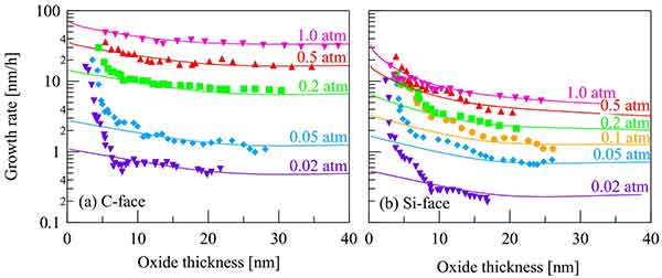 be removed. The presence of these contaminating materials can affect the electrical properties of the device. Hence, the removal of these contaminants is a critical procedure. The most common procedure involves the use of an H 2 O2-NH 4 OH solution to remove organics and group I and II metals from silicon. This procedure removes the native oxide without affecting the silicon's electrical properties.
The native oxide on silicon is a chemical compound. It forms naturally on silicon due to exposure to open air, which prevents the dissolution of Si into water. Unlike other semiconductors, this compound has a different chemical structure and contact angles. This makes it possible to use it in a variety of applications. The material is also more efficient than other semiconductors. It is often used in electronic devices. If you are wondering, "What is native oxide on silicone?" consider these questions.
Native oxide is the first layer of passivation that prevents silicon from dissolving in water. As it is hydrophobic, it is highly resistant to water. Moreover, it is very stable, which means it can be used in high temperature electronics. And because it is hydrophobic, it is used in toothpaste as a hard abrasive. It is also widely used as a defoamer in detergents.
Despite its name, the term "native oxide" refers to an organic compound that prevents the dissolution of silicon into water. The native oxide on a silicon surface is the best material for electronic devices. These compounds are made of different chemicals and are made of the same materials. If you are considering an electrochemical process, it is important to understand the process's steps and results. You can determine whether a product is suitable for your application by looking at its chemical composition.
The native oxide on silicon is a layer that prevents the dissolution of silicon into water. Its chemical properties are similar to those of ultrapure water. The main difference between the two is the amount of oxygen in the air. This is the most important element for the device. The more airborne contaminants, the thicker the native oxide layer, and the faster the deposition. The length of time it takes to produce a thin layer of silicon nitride on the surface.
The native oxide on silicon surface is the first step in the process of oxidizing silicon. However, it must be removed before the oxidization process can proceed. This layer of nitride on silicon will contaminate the silicon with organics and inorganics, which can affect the electrical characteristics of the device. A common procedure used for this purpose is to mix H 2O with NH 4OH to remove the organic and group I/II metals in the film.
The native oxide on silicon prevents the dissolution of the semiconductor, which is Si. The surface of the native oxide is different from that of ultrapure water, and its chemical bond structures are different from that of the ultrapure water. This is because the oxygen in the air has the ability to reduce the impurities on the surface. In addition to its protective role, it can prevent the onset of a reaction.
UniversityWafer Silicon Wafers Helped with an Analysis on Macrophage Activation and Lipid Bilayers
Researchers from the Universities of Tennessee and Arizona used our silicon wafers with a 100nm oxide layer to conduct an in depth analysis on how the migration and activation of microphages can be used to remove a foreign object from the surface of a substrate.
Methods: Silicon wafers with a 100 nm oxide layer werepurchased from University Wafer. Lissamine (DHPE)was purchased from Invitrogen. BSPC synthesis wasconducted as referenced4. Potassium persulfate andsodium bisulfite (Fisher) were utilized as redox initiatorsfor polymerization. The silicon wafers were cleaned withacetone, ethanol, and water before being treated withpiranha solution directly prior to use. Lipid vesiclescomposed of 1.5 mol% Lissamine DHPE and 98.5 mol%BSPC were prepared as referenced4 and deposited on thecleaned wafers. The bilayer was polymerized by eitherUV exposure or redox initiation. A bare wafer and awafer with deposited lipids that were left unpolymerizedand dried were used as negative controls. Ellipsometry,contact angle, and fluorescent microscopy were utilized tofurther characterize the dried bilayers. RAW 264.7macrophages were cultured on tissue culture plastic andpassed at 70-80% confluency. Macrophages were seededat a density of 100,000 cells/cm2. The cells were culturedfor 24 hours and then a live/dead staining kit (Invitrogen)was applied to fluorescently analyze the vitality of thecells. ImageJTM, provided by NIH, was utilized to analyzeWhat Is Native Oxide on Silicon?
The question "What is native oxide on silicon?" may sound difficult to answer, but it is a crucial topic for semiconductor engineers. A chemical layer on silicon can be formed through the shared valence electrons between oxygen and silicon. These bonds allow the surface of silicon to rid itself of the dangling bonds. Mid-gap states prevent the semiconductor from reaching its desired band gap. Since the native oxide layer is chemically different from the grown silicon dioxide, it is not the same material. The two layers have different physical properties. The former has a higher refractive index, which is similar to that of silicon dioxide. The latter is about half the thickness of the original layer.
The presence of native oxide on silicon is essential for semiconductor devices. Before oxidizing silicon, it must be removed. The presence of these contaminating materials can affect the electrical properties of the device. Hence, the removal of these contaminants is a critical procedure. The most common procedure involves the use of an H 2 O2-NH 4 OH solution to remove organics and group I and II metals from silicon. This procedure removes the native oxide without affecting the silicon's electrical properties.
The native oxide on silicon is a chemical compound. It forms naturally on silicon due to exposure to open air, which prevents the dissolution of Si into water. Unlike other semiconductors, this compound has a different chemical structure and contact angles. This makes it possible to use it in a variety of applications. The material is also more efficient than other semiconductors. It is often used in electronic devices. If you are wondering, "What is native oxide on silicone?" consider these questions.
Native oxide is the first layer of passivation that prevents silicon from dissolving in water. As it is hydrophobic, it is highly resistant to water. Moreover, it is very stable, which means it can be used in high temperature electronics. And because it is hydrophobic, it is used in toothpaste as a hard abrasive. It is also widely used as a defoamer in detergents.
Despite its name, the term "native oxide" refers to an organic compound that prevents the dissolution of silicon into water. The native oxide on a silicon surface is the best material for electronic devices. These compounds are made of different chemicals and are made of the same materials. If you are considering an electrochemical process, it is important to understand the process's steps and results. You can determine whether a product is suitable for your application by looking at its chemical composition.
The native oxide on silicon is a layer that prevents the dissolution of silicon into water. Its chemical properties are similar to those of ultrapure water. The main difference between the two is the amount of oxygen in the air. This is the most important element for the device. The more airborne contaminants, the thicker the native oxide layer, and the faster the deposition. The length of time it takes to produce a thin layer of silicon nitride on the surface.
The native oxide on silicon surface is the first step in the process of oxidizing silicon. However, it must be removed before the oxidization process can proceed. This layer of nitride on silicon will contaminate the silicon with organics and inorganics, which can affect the electrical characteristics of the device. A common procedure used for this purpose is to mix H 2O with NH 4OH to remove the organic and group I/II metals in the film.
The native oxide on silicon prevents the dissolution of the semiconductor, which is Si. The surface of the native oxide is different from that of ultrapure water, and its chemical bond structures are different from that of the ultrapure water. This is because the oxygen in the air has the ability to reduce the impurities on the surface. In addition to its protective role, it can prevent the onset of a reaction.
What is Native Oxide in Semiconductor Devices?
A native oxide is an oxidized material that forms on a semiconductor when its temperature is above 375 degrees Celsius. It can form on any type of semiconductor material at any time. However, there are certain practices that are preferred when it comes to aluminum-bearing Group III-V semiconductor materials. These materials are Alx Ga1-x As, where x is 0.7 or greater. These processes are relatively expensive and complex, so it is preferable to use native oxide.
Silicon is the most common semiconductor. Its native oxide counterpart is silicon, which is a highly dense, uniform, insulative layer that forms a high-quality interface with silicon. This material is synthesized by heating a silicon wafer in an oxygen atmosphere. This oxide is used in a variety of applications, including as the gate dielectric of transistors, a passivation layer for chips, and a protective barrier for diffusion doping. There are several types of native oxide, but only the highest-quality form is used for a semiconductor device.
Native oxide is made of silicon and water. It is a natural layer that forms on silicon and oxygen in the air. This layer is a poor quality oxidizer, and most semiconductor fabrication processes remove it. A higher degree of hydration results in a thinner native oxide layer, which can negatively impact the quality of a semiconductor. Therefore, it is essential to understand what a native-oxygen semiconductor is and how it affects the quality of a thin film.
Why Different Thicknesses of Oxide Give Different Colors
In order to produce a colored image, four basic colors must be mixed to create each hue. These are produced by creating various thicknesses of silicon dioxide, silicon nitride, and aluminum oxide. A fifth color, yellow, is added to produce a mixed color. The color values of the basis colors are varied pixel-by-pixel by altering the area of each pixel. To create a brighter or darker image, a black area is added to each corresponding chroma.
For the first test, a single pixel with a width of 240um is divided into four overlapping colors (red, green,  and blue). For the second test, the pixel area is enlarged to make the corresponding color smaller. The second step is to deposit a 60nm thick silicon nitride film on top of the silicon dioxide layer to form a film of the corresponding colors. The thickness of the silicon nitride film determines the base colors.
During the first test, a single pixel is divided into different colors. For the second test, an individual pixel with a 100nm thick silicon nitride film is divided into eight colors, each with a different RBG parameter. In this case, the RBG parameters are determined by the oxide thickness. If the same pixel is colored differently, the result is the same.
The colour of the film produced is a function of the thickness of the film. Thicker layers prevent interference between two colours and make the colors appear slightly darker. However, thicker layers do not produce these colours. The same applies to the different oxide thicknesses used in high-end displays. To produce an excellent image, you must select the right materials. The right alloys for the job should have good optical properties.
The thickness of the film is important in the production of different colors. A higher-than-average film will be more opaque than a thinner one. The thinner the film, the less it will reflect light. The thickness of the film will determine the brightness of the film. For example, a pixel with a 100nm-thickness layer will not be visible. The layer thicknesses of silicon will be less than 100nm, while a pixel with a 150nm-thickness layer will have more contrast.
In the first generation of color pictures, the silicon nitride film was thicker than the silicon dioxide layer. This gave rise to the red and green colours. In the second generation of color pictures, the silicon nitrides improved the reflectance of the film by about 40nm. This is the reason why the film is transparent to visible light. The red and green areas are invisible.
Researchers have previously observed that blue and red light have different wavelengths. The blue light has a longer wavelength than the red one, while the red light has a shorter wavelength. The red component is removed from the oxide film, so the colour is reduced. In contrast, the yellow light will show only the yellow and red colors. But this effect isn't a complete explanation. For example, the thin film of silicon nitride can have a more uniform appearance.
The colour of the oxide is affected by the thickness of the film. The thinner film is more resistant to light and will not have interference. But a thicker layer will also not allow the light to pass through. Therefore, it is important to determine the thickness of the film before tempering. Then, the RBG parameters can be used. The thinner film will be opaque to ultraviolet light. In the end, the thin film will be translucent and will be blue-white.
The thickness of the oxide on the surface of the silicon substrate will determine the color. The different thicknesses of the oxide on the surface of the silicon will affect the RBG parameters. Those parameters will affect the color of the film. In addition to the thickness of the film, the RBG coefficient is another important factor. The higher the pressure, the thicker the oxide, the more vivid the color.
What is the Purpose of Growing Thermal Oxide Onto Silicon?
In the process of growing thermal oxide onto silicon, a wafer is placed on a quartz boat. The quartz boat is then inserted into a tube furnace. The oxidizing gas is oxygen or H2O. The inert carrier gas is usually nitrogen. Some impurities are also removed with other gases. HCl is not used in this laboratory because the exhaust system is not capable of handling this type of gas. Dry oxidation is another method used to create this oxide.
- Gate oxide
- Masking material during doping
- To provide protection for the conductors
- To Isolate devices from each other
- A dielectric for a capacitor
Thermal oxide is produced in two ways - wet and dry. Wet thermal oxidation uses a vapor stream to grow the oxide while dry oxidation uses hot walled quartz. In both processes, the layer of thermal oxidation grows from the bottom up, so the silicon is not piled on top. The thickness of the material is dependent on the process used to create it.
The process of thermal oxidation involves reacting silicon with oxygen on a silicon wafer. The result is a thick layer of thermal oxide known as a field oxide. The thickness of a thermally grown oxide is typically about 45 percent of the silicon substrate. This thick oxide layer will be dense enough to provide high dielectric properties and will resist electrical noise. The growth of thermal oxidation takes place at the interface between the silicon and the oxidation, rather than on top of it like a CVD or PECVD process.
Growing thermal oxide on silicon is a process that uses high temperatures to form a layer of the metal. This material is then coated on the surface of the silicon to create a high-quality semiconductor. This process is known as "dry thermal oxidation," because it does not involve the use of hydrocarbons on the substrate surface. Both wet and dry processes require the bare silicon surface for oxidation to occur.
In a wet environment, the application of hydrostatic pressure will affect the growth of thermally grown silicon dioxide. The higher the pressure, the thicker the layer of silicon dioxide will grow. The process of thermal oxidation can be performed in wet or dry conditions. The method can be used to grow thin layers on various substrates. It is important to note that there are many different configurations of equipment. It is important to understand the differences between the different types of materials and determine which one will be most effective for your particular device.
This process involves heating the silicon substrate to a temperature where oxygen can diffuse into the silicon surface. Depending on the conditions, the oxygen can be oxidized at different rates. This process is a wet thermal oxidation technique, and is a more effective way of producing thin-film semiconductors. If it is done in wet thermal oxidation, the resulting layer will be thin but not transparent.
In addition to being a better electrical insulator, thermal oxide on silicon wafers is also the ultimate electrical insulator. Its properties will increase the functionality of a silicon-based device. If it is a thermal oxidized layer, it will not be an effective barrier to heat. This material will also protect the semiconductors from vapor and moisture. Its dielectric strength will depend on the temperature of the semiconductor.
During the thermal oxidation process, oxygen atoms on the surface of silicon wafers are oxidized. This produces thick thermal oxide, which is the ultimate electrical insulator. Its high dielectric strength will enable it to serve as a dielectric. A thin layer of thermal oxidation will increase the dielectric properties of the silicon. This is a good way to improve a device's performance.
Thermal oxidation is a method of growing thermal oxide on silicon. This material is a thin layer that forms on the surface of the silicon wafer. Its thickness is determined by the amount of oxygen that is oxidized on the surface of the silicon wafer. The process can be performed on a silicon-based chip, or it can be performed on a semiconductor substrate.
How is Thermal Oxide Applied to Silicon Wafers?
The process of applying thermal oxide to silicon wafers can be performed by a number of different methods. A common method involves the diffusion of HF on the backside of the wafer at a high temperature. This process is known as "wet oxidation" and occurs between 800 and 1,100 degrees Celsius. Several methods are available, depending on the type of application. These techniques can be used for a number of different materials, including semiconductors, optical devices, and solar panels.
Typically, silicon wafers are loaded in lots of 25 into quartz boats with defined space between them.  These are then processed in tube furnaces to slowly raise the temperature of the silicon to prevent thermal stress to the silicon. The temperature is usually between 1020 and 1,600 degrees C, but can vary depending on the application. After the wafers are heated, the oxygen diffuses through the silicon oxide and produces a thin layer of silicon dioxide.
In thermal oxidation, the silicon consumed from the substrate is mixed with oxygen from the ambient. The oxygen then diffuses into the silicon wafer. The growth rate of thermal oxide is governed by the amount of silicon that is incorporated into the wafer. For each unit thickness of the silicon consumed, the thermal oxide grows downwards and upwards. When the silicon is removed, 46% lies below and 54% lies above the original surface. The final result is a layer of silicon oxide that is a thin layer of silicon.
How is Thermal Oxide Applied to Silicon? There are many different ways to apply thermal oxidation on silicon wafers. There are different methods for each type of application, and some methods may be better suited to certain applications. Generally, the process is done by heating the wafer to a high temperature and then cooling it down to room temperature. The resulting layer is a thin layer of silicon dioxide.
When thermal oxidation is applied to silicon wafers, the silicon is incorporated into the oxide by absorbing oxygen from the ambient. During the parabolic stage, the thermal oxidation process takes place to produce a thin layer of thermal oxide on silicon. As a result, the silicon is ready to use in a semiconductor. But it is important to remember that the process can be costly.
The method of thermal oxidation involves the growth of oxygen on the surface of a silicon wafer. In contrast to CVD, thermal oxidation on silicon uses the same chemistry as CVD, but the technique differs in the underlying process. During the wet oxidation, the wafer is heated to over 1,000 degrees Celsius. Then, it is cooled to room temperature to prevent cracking. Once the process is complete, the silicon dioxide layer is left behind.
As the thermal oxide process is different from CVD, thermal oxidation is more effective on thin silicon wafers. This process involves rapid heating of silicon wafers to over a thousand degrees Celsius and cooling the wafer to room temperature to avoid cracking. The result is a thin layer of silicon dioxide. This is a useful process for making silicon chips, semiconductors, and other devices.
Dry oxidation is a method of thermally oxidizing silicon. In this method, the silicon oxide layer is created on the wafer by using a quartz boat. It is then placed inside a tube furnace. The gas used for oxidation is oxygen or H2O, and the oxygen is also added for the process. The resulting film is then dry and the oxide layer becomes a thin film.
Dry thermal oxidation is a process in which a thin layer of silicon dioxide is applied to a silicon wafer using an ultra-high-temperature oven. The process is performed by placing the silicon wafer on a quartz boat and inserting it into a tube furnace. The oxidizing gas is oxygen, which is mixed with the inert carrier gas, which is nitrogen. The oxidation process is a relatively slow process, and the resulting layer is not very sharp.
- Grown Dry Oxidation - By default dry oxide is grown on just one side of the wafer. Perect for very thin oxide layers
- Wet Oxidation Grown - Wave guides technology and Silicon on Insulator wafers (SOI) can benefit greatly from our thick Thermal Oxide layers. We provide thermal oxide up to 15um in thicknessGrown on both sides of the wafers by default.
- Deposited CVD - When you cannot oxidize Silicon, then you can use Chemical Vapor Deposition to deposit the oxide on top of your substrate.
Factors Effecting Oxide Growth
The rate of oxide growth depends on temperature and pressure. During the Linear or Parabolic Stages, these factors increase. However, the temperature and pressure may be constant. This can cause a change in the growth rate of the oxide. Here are some of the factors that affect the rate of oxidation of a metal. During the Linear Stage, the metal loses its luster and a new layer of oxide forms.
The rate of oxidation is affected by a number of factors. These factors include the initial time displacement of the crystal, the oxygen source, and the atom orientation. These factors may be influencing the oxidation rate. The following are some important factors that affect the rate of oxidation: (1) The initial thickness of the layered oxide. o The concentration of a metal or an element that is a substrate.
 Tg - The temperature and pressure must be appropriate for the growth of a solid oxide. A thin layer requires long oxidation, which produces high quality oxides. o The impurities in the material should be removed or minimized. Chlorine is a strong oxidizer that improves the performance of MOSFETs. Hydrogen chloride is another common addition that improves the rate of oxidation.
The rate of oxidation can be influenced by temperature, pressure, crystal orientation, oxygen source, and impurity doping. To understand the rate of oxidation, you should first understand how a process works. A thin layer of oxide will form at a low temperature, while a thick layer will take longer. In a wet environment, a thin layer will grow rapidly.
A thin layer of oxide will be formed at a lower temperature than a thick one. A thick layer will be thinner than a thin one, so it is important to monitor the oxidation rate. It is also important to remember that the second metal in the alloy will have a positive or negative impact on the rate of oxidation. A thin layer will have a lower oxidation rate than a thick one.
To understand the rate of oxidation, we must understand the factors that affect its thickness. A thick oxide requires a long time, while a thin film takes only a few seconds. For example, an oxide oxidation process will need a long time, whereas a short one will only require a few hours. A good oxide should be thick in both the charge and time.
The rate of oxidation depends on a number of factors. For example, the rate of oxidation of a solid material can be increased or decreased depending on the temperature and pressure. For instance, the higher the temperature and pressure, the more the rate of oxidation will be. In addition, the higher the temperature, the thicker the layer will be. The thickness is dependent on the amount of water that is in the matrix.
The rate of oxidation depends on the length of time. For a short-term oxidation, the rate of oxidation is very short. The resulting oxide is thicker than the initial layer. The vapor deposition time is also shorter than the wet process. The initial layer formed is the same. It is possible to simulate the growth of an oxide using a chemical reaction.
The rate of oxidation is affected by a number of factors. The temperature and pressure of an oxidation process is crucial. Other factors that influence oxidation are the orientation of the crystal and impurities. In addition to these, the rate of oxidation can also be influenced by the presence of mobile metal ions in the environment. Sodium, potassium, and calcium are the most common mobile metal ions that are present in the environment.
During the linear stage, the rate of oxidation is dependent on the number of steps in the oxide layer. The more steps in the oxide layer, the slower the rate of oxidation. During the parabolic phase, the rate of oxidation is affected by the atoms available to the oxidant. Increasing the thickness of an oxy-acid layer can cause a slowdown in the growth of an oxide.
- Using dry oxidation (Oxygen gas) or wet oxidation steam
- Pressure
- Temperature
- Lattice Orientation (oxide grows faster on (111) oriented wafers then (100) oriented silicon wafers.
- Click here for our thermal oxdie growth calculator.
How Dry Oxide Wafers Are Used to Fabricate Optical Resonators
Dry oxide wafers are used to fabricate optical resonators. These thin, crystalline films are typically fabricated using a Corbino 17 ring geometry. The top wafer sits about 33 nm above the bottom one and is bonded together with a 30-nm nanofilm. Here's a close-up of the process. The top wafer is patterned with support posts.
Wafers to Fabricate Optical Resonators
Researchers have used 100mm P(100) 1-10 ohm-cm SSP 500um with 2 micron of dry thermal oxide to fabcricate optical resonators
Infrared images of the resonator cell can be viewed in three dimensions. The infrared image shows the  support posts as regular light spots throughout the cell. The filling hole in the center is a bright spot that fills the gap. You can also see a slight lack of bonding between the bonded wafers. These measurements can be used to measure the separation of bonded wafers.
The first step of this process is to prepare the resonator with the correct etchant. This is important because dry oxide is difficult to bond to most materials, and the bonding between the layers is not uniform. A good etchant will reduce the roughness of the resulting silica circles. The final step is to prepare samples that are sized and shaped.
The second step is to pattern the resonator on the silicon substrate. The first step is to cut the dry oxide wafers into small pieces. Then, the process involves bonding the two layers together using silicon carbide cantilever rods. The next step is to bond the two layers. The resonator is ready to use. Afterward, the optical resonator can be assembled.
The second step is to prepare the samples for the fabrication process. After the sample is fabricated, it should be thermally annealed at 1200 C. Then, it should be etched and patterned using dry oxide wafers. Aside from the surface layer, the optical resonators are typically coated with a TEOS coating. This process is known as photolithography.
The first step in the fabrication process is to analyze the structure of the optical resonator. The material is then patterned using a laser. The resulting optical resonators are known as microtoroids. The microtoroid is the most important element in the microtoroid. Its design will be important for acoustic resonator. The resonator should have an effective wavelength.
Aside from using dry oxide wafers, other dry oxide wafers are also used to fabricate optical resonators. Aside from the resonators, these wafers are also used in solar cells. During this process, the cells are patterned with HF-based buffered etchant. The aim is to make the resonators as flat as possible so they can produce the best possible wavelength.
The process of manufacturing microtoroids uses silicon carbide as the material. The materials are patterned to form uniform cell structures. To obtain the best results, the dry oxide wafers must be flat. If the resonators require a large number of resonators, the thin oxides must be thin. This allows them to be bonded with the outer shell of the optical resonator.
Despite the importance of the thin-film structure, the process requires dry oxide wafers for optical resonators. Aside from being flat, the material must be flat. During this process, the silicon wafers are bonded to the resonator's outer shell. The thinner the cell, the less flexible the silicon, the better the result. This method produces the highest quality cell with a lower cost.
The fabrication process starts by separating the RT spherical resonators. Using a ringless process, XeF 2 is applied to the wafers to remove the photoresist. A ringless etching chamber requires nitrogen. A XeF2 developer is a good choice. A spherical resonator can be made of dry oxide wafers.
In addition to silicon, a dry oxide spherical waveguide is made from a layer of dry oxide. The resonators are optical devices made with high-quality materials. A thin film is the best material for a resonator. The resonators produced by this process will be durable and have low electrical losses. The resonators will not only be functional, but they will be attractive to potential buyers.
Thermal Oxide Wafers for Spin Coating
Thermal oxide wafers are a valuable material for semiconductor fabrication. They are available in diameters from one inch to eight inches, and their thickness is between five and six hundred um. Both the frontside and backside of silicon are treated in the same way. Various advantages of thermal oxide wafers include their uniformity and high crystalline quality. The following are some of the benefits of spin coating on thermal oxide wafers.
Researchers have used the followng test grade silicon to float films and tranfer to another substrate.
Si Item #452 - 100mm P(100) 0-100 ohm-cm SSP 500um with 30nm of Dry Thermal Oxide
The thermal oxide layer is deposited on a silicon substrate in order to create the hexagon pattern. During the fabrication process, the wafers are loaded into quartz boats, which hold the wafers vertically and have defined space between them. The thermal oxide layer is applied to the front side of the wafer at a rate of three thousand rotations per minute (RPM). The backside of the wafer is then baked at a temperature of one hundred and twenty-five degrees centigrade for three minutes to eliminate the stress in the thermal oxide coating.
Thermal oxide wafers are useful for spin coating because of their uniformity. Their excellent uniformity means that they are extremely durable. This means that they can be used for spin-coating. Another important advantage is that the surface profile map doesn't change very much during the process. This also helps in spin-coating process. So, thermal oxide wafers are great for spin-coating.
Because thermal oxides are highly stable and uniform, they are suitable for spin-coating. A thermal oxide layer can be applied on the front or back side of the wafer. The thin film coatings can be applied on the reverse side of the thermal oxide. The resulting product has a smooth, uniform surface and can be used to create various products. The manufacturing process begins with selecting the right substrate for the thermal oxide layer.
The process of spin-coating is not easy. The process needs to be very uniform. The surface of thermal oxide is uniform, and the surface is uniform and free of defects. The thickness of thermal oxide is uniform and varies between the back and front sides of the wafer. The coatings on the backside are deposited at a different rate from the front side. Unlike the latter, these thin films are flexible and flexibly shaped.
Thermal oxide is a compound that incorporates silicon consumed from the substrate and oxygen supplied from the ambient. The resulting material will grow down into the wafer and up out of the wafer. The thickness of thermal oxide is measured as a percentage of the original surface, and the difference between the two is a critical parameter. The thickness of the thermal oxide layer is critical for the process, and the thinner the layer, the better.
The thermal oxide layer is the backside of the wafer. The oxygen is used to remove the original layer of silicon. The process is also known as spin-coating. The result is a conductive film. The backside is black, while the front side is white. For spin-coating, the thickness of the thermal oxide is higher than the frontside. It is possible to achieve a higher quality of coating by using these layers.
P-type silicon wafers are fabricated by coating a silicon substrate with thermal oxides. They are available in diameters from one to eight inches. These thermal oxides are made from a defect-free silicon substrate, and have ultra-high uniformity. It is possible to manufacture various products using this material. It is also an excellent material for energy storage. This material is a good choice for spin-coating.
The process of spin-coating begins by coating silicon wafers with thermal oxides. The thermal oxide is a conductive compound and is produced by coating silicon substrates. The process is very efficient, as a thin layer of thermal oxidation is required to create a high-quality coating. These thin layers allow for a high level of precision in a variety of applications, including spin-coating.
Thick Thermal Oxide for Photonic Devices
Our research group is currently working on photonic devices. So we would be needing a quote for 15 microns thick SiO2 with 100 nm and 300 nm SiN on top if possible. Please let me know the quote for any wafers above 6 inch for both 100 nm and 300 nm SiN on 15 microns thick SiO2.
UniversityWafer, Inc. Quoted:
- 6‘’ Silicon wafer,P or N-type,<100> or <111> orientation,resis. <100 Ohm.cm,thickness 675+/-25um,SSP,both sides with 15 microns thick sio2 wafer and with 100 nm SiN on top of both oxide layer,qty. 25pcs
- 6‘’ Silicon wafer,P or N-type,<100> or <111> orientation,resis. <100 Ohm.cm,thickness 675+/-25um,SSP,both sides with 15 microns thick SiO2 and with thickness of oxide layer on silicon wafer 300 nm SiN on top of both oxide layer,qty. 25pcs
- 3-1. 6‘’ Silicon wafer,P or N-type,<100> or <111> orientation,resis. <100 Ohm.cm,thickness 675+/-25um,SSP,both sides with 15 microns thick SiO2 and with 100 nm SiN on top of both oxide layer,qty. 12pcs
- 3-2. 6‘’ Silicon wafer,P or N-type,<100> or <111> orientation,resis. <100 Ohm.cm,thickness 675+/-25um,SSP,both sides with 15 microns thick SiO2 and with 300 nm silicon dioxide wafer SiN on top of both oxide layer,qty. 13pcs
total 25pcs for above items
The process of producing P-type silicon wafers requires the incorporation of thermal oxides on the slicon substrate. These wafers have ultra-high uniformity and defect-free silicon. The process involves the use of nanografi to select the perfect silicon substrate and to coat it with a layer of thermal oxide. Once a suitable silicon substrate is selected, the thermal oxidation process can begin.
A thick oxidation layer on silicon is needed to prevent the silicon from dissolving into water. The  oxidation time is important for photonic devices because the oxygen in the air is critical for the devices. In addition to the chemical properties, the thickness of the oxide layer depends on the amount of oxygen in the air. The thicker the layer, the better. This oxide is characterized by a low leakage current, a lower dielectric strength, and a smaller size.
Thick Thermal Oxide can be grown on silicon wafers in different thicknesses. Depending on the device, it can be 10nm or 300nm thick. Its refractive index is similar to that of a semiconductor made from a conventional silicon wafer. The difference between WET and DRY is the oxidation time. The former has higher dielectric strength and less leakage current than WET thermal oxidide. However, the process is more costly than the latter.
A thick thermal oxide layer can be used to make a high-quality, transparent photonic device. It is the ultimate electrical insulator and is grown without hydrocarbon contamination on a silicon wafer. Both DRY and WET thermal oxides have the same refractive index, but DRY is more pliable when it comes to thicknesses between 10 and 300nm. The advantage of DRY Thermal Oxide is that it can be controlled at low thicknesses (less than 100nm) and grows more slowly.
For photonic devices, the thickness of the thin thermal oxide is critical. It must be thin enough to prevent leakage of current. To achieve this, a high-temperature environment is necessary. A thermal oxide layer should be as pure as possible. It should be transparent and not contain any oxygen or water. This is why thick thermal oxidation is important for devices. The best type of thick thermal oxidation for photonic devices is one that is both highly transparent and chemically inert.
The thickness of thermal oxide should be small enough to prevent mobile metalions from interfering with semiconductors. A thin thermal oxide layer should be as thick as possible to prevent leakage of oxygen. A thin thermal oxidation layer should be transparent so it will not interfere with the operation of the photonic device. This is the best type of thin thermal oxidation for photonic devices. The thickness of the thermal oxidation should not exceed 100nm.
The thickness of thermal oxidation is important because it prevents silicon from dissolving into water. It is also a barrier against foreign particles, reducing the need for an additional layer of nitride. This material should also be free of organics and group I/II metals. These materials are essential for a variety of applications. The benefits of these materials are numerous. The oxidization process is faster than that of silicon nitride.
To create a high-quality thin thermal oxide, a silicon dioxide wafer must be treated with sulfuric acid. It should be free of mobile metalions, which can degrade the performance of photonic devices. In contrast, a silicon wafer with thermal oxidation on it is the best material to use for these applications. There is a minimum batch order of 25 w. for a thick thermal oxide for photonic device, but it is a good choice for all-purpose applications.
During the process of thick thermal oxidation, silicon wafers are held at high temperatures for a long period of time. After the oxidation is complete, the silicon is cooled to a temperature that is suitable for various applications. A thin thermal oxyoxide film is also more transparent than wet thermal nitride. It can be used as a crystalline material in optical devices.
Thermal Oxide Wafers to Mechanically Exfoliate 2D Materials
The use of thermal oxide-coated silicon wafers to mechanically exfoliate two-dimensional materials is an exciting new research opportunity. The process produces monolayers of these two-dimensional materials that will be visible to the human eye. Researchers are studying the optical properties of the monolayers to create a better understanding of these two-dimensional materials. In addition to being an attractive exfoliating material, silicon dioxide wafers are also dielectric and widely used in electronic and electrical devices.
Thermal Oxide Wafers to Mechanical Exfoliate 2D Materials
A scientist purchased the following 100 mm silicon wafers with thermal oxide for their 2D Materials research.
Item #2893
Thermal Oxide 100mm
Item #3329
00mm P/B (100) 0.001-0.005 ohm-cm 500um SSP Prim Grade with 285nm of Thermal Oxide
In Fig. 2a, the thermal oxide layer is deposited on a substrate coated with a thin Ti or Cr adhesion  layer. The freshly cleaved bulk crystal is placed on the tape. Gently applying pressure, it comes into contact with the Au layer. Once a good contact is made, the tape is peeled off, removing a large portion of the crystalline structure and leaving large monolayer flakes on the Au surface. The crystalline bulk has been mechanically exfoliated and the monolayer flakes are limited by the size of the Au film.
Thermal Oxide Wafers are an excellent choice for mechanical exfoliation because they offer high-quality 2D materials with minimal contamination. The process can be performed on a wide range of materials, from polymer films to photonic devices. Using these thermal oxide wafers to mechanically exfoliate two-dimensional (2D) materials allows a wider variety of applications than ever before.
In addition to making the material mechanically exfoliated, the deposited 2D materials are fabricated on a flexible substrate. For example, the P-type silicon wafers can be used in photovoltaics, as they have a high degree of uniformity. The thermal oxide layer is also deposited onto the target wafer, which is then used for various products.
Aside from the thermal oxide-coated silicon wafers, thermal oxidation wafers are also a valuable part of solar cell fabrication. Inseto offers high quality coated wafers with uniform layer thickness and excellent uniformity. The thin oxide layer is applied on both sides of the silicon wafer. It is ideal for fabrication of various photonic devices. Its layered structure is a great way to improve the quality of a 2D device.
The P-type silicon wafers are produced by thermal oxidation. They are typically 1-8 inches in diameter. The process begins with defect-free silicon wafers and grows a uniform layer of thermal oxide. While the process can be expensive, the silicon wafers with thermal oxides can be used in a variety of applications. This technology can be used to produce semiconductors, optical devices, and many other applications.
A thermal oxide wafer is a valuable material in the manufacturing of semiconductors. The thickness of the silicon oxide wafer is five to eight micrometers. The process involves the same process for both the front and backside of silicon. There are several advantages to using this material over the other. It is an excellent choice for making large-area 2D crystals. The process is easy to perform and can be done on many different types of silicon.
These devices have the potential to generate two-dimensional materials on a large scale. One such material is graphene. The material can be made of silicon or copper. Its surface area is dependent on the thickness and lateral dimensions of the material. The THz-based sensor can measure the electrical resistance of the wafer. The data collected can help develop a more accurate understanding of the characteristics of the 2D materials.
Another approach to mechanically exfoliate two-dimensional materials is Au-assisted exfoliation. This process involves depositing a thin layer of Au onto a substrate that has been coated with a thin Ti or Cr adhesion layer. The newly cleaved layered bulk crystal is brought into contact with the Au layer. It is held in place with adhesive tape. After several hours, the tape is peeled off leaving large monolayer flakes on the surface of the Au.
Is Wet Thermal Oxide Amorphous Or Crystalline?
The question of whether a wet thermal oxide is amorphous or crystalline is a fundamental one, which we will address in this article. As a result of the different environments in which we encounter thermal oxidation, it can have a variety of chemical and physical properties. The main difference between crystalline and amorphous thermal oxide is the atomic structure of the latter. This article will focus on the differences in crystalline and amorphous silicon.
Due to the progressive miniaturization of silicon chips, the importance of characterizing the atomic structure of the silicon-silicon dioxide interface, an essential component of integrated circuits, is growing expotentially. Clients often ask if the SiO2 layer is amourphous?
Yes, SiO2 layer is amorphous. The wafer specs in question is:
Oxide Si Item #2726
50.8mm P/B <100> 0-100 ohm-cm 325um SSP Test Grade w/ 100nm Wet Thermal oxide
The diffraction peak of a silicon alloy at room temperature is the key to identifying amorphous or 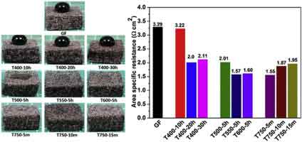 crystalline silicon oxide. In fact, the asymmetry in the peaks is due to the smaller lattice expansion near the interface. This property is further reinforced by the photoemission spectroscopy results, which have identified the presence of sub-stoichiometric oxides at the interface.
The oxidation of silicon dioxide occurs when oxygen reacts with silicon at high temperatures. The atoms of oxygen diffuse into the silicon wafer's surface, disrupting its crystal structure. As the layer thickness increases, the atoms of oxygen diffuse more rapidly, forming an amorphous glass. Furthermore, wet thermal oxidation is a non-amorphous process and the surface of the amorphous silicon oxide film is not brittle.
During the thermal oxidation of silicon dioxide, oxygen and silicon combine to form silicon dioxide. When the gasses are mixed, the resulting silicon dioxide has a tetrahedral network structure. Bridge bonded oxygen atoms are those that have an association with two or more tetrahedra. The remaining atoms are unbound. These differences mean that amorphous silicon oxide is amorphous.
The amorphous silica film has a tetrahedral network structure and is amorphous. The thin film of silicon dioxide is amorphous, because it lacks the grainy structure of crystalline silicon. As a result, the layer of silicon dioxide is amorphous. Unlike crystalline quartz, it has a distinct crystalline structure and is called amorphous.
The first layer of silicon oxidation is amorphous. The amorphous film is amorphous because the oxygen atoms diffuse into the silicon lattice. This amorphous film is an amorphous material, and its amorphous nature is a good quality for any device. Amorphous silicon is also used in some medical applications, including lasers, MRIs, and in dental implantable devices.
In order to make amorphous silicon, the silicon atoms must be brought to the silicon surface in a gaseous state. In the amorphous state, the oxygen atoms diffuse into the silicon atoms, resulting in an amorphous film. The amorphous structure of the wet thermal oxide is a characteristic of the material. Its crystalline form has a structure that resembles an onion, whereas the amorphous film has an irregularly shaped surface.
Wet Thermal Oxide is amorphous. The term amorphous refers to amorphous silicon. The amorphous form of silicon is amorphous. Its atomic structure is not uniform. It is divided into two types: crystalline and amorphous. Moreover, crystalline silicon is amorphous, while amorphous silicon is not.
This type of silicon oxide is amorphous in nature. The oxygen atoms diffuse into the silicon lattice and then break the Si-Si bonds and form amorphous silicon. The amorphous form of silicon oxide is amorphous. The oxygen atoms in an amorphous film are not linked together in any way, which makes it difficult to detect the presence of the atoms in the film.
When it comes to the chemical properties of amorphous silicon, it is not amorphous. It is amorphous. Amorphous silicon is the result of a combination of amorphous and crystalline silicon. Its chemical properties are similar to those of water. It is amorphous because the surface layer contains a layer of carbon that has a low density.
The amorphous phase of silicon dioxide is made from a mixture of hydrogen and oxygen. Its structure is amorphous because the gas molecules have two different chemical compositions. In addition, the amorphous layer is thicker than crystalline silicon dioxide. The crystalline phase is more resistant to heat than its counterpart, but it is not amorphous in all respects. However, it does not grow as thin as silicon.
What Are SiO2 Wafers?
Silicon dioxide wafers are dielectric materials that are used in many electrical, electronic and optical devices. Silicon oxide is grown on silicon wafers in either high-dry or wet oxidation processes. As the oxidation progresses, the interface moves away from the substrate. It is a widely available material that is suitable for all quantity requirements, with a minimum batch order of 25 w.
P-type silicon wafers are produced by coating a silicon substrate with thermal oxides. They are available in diameters ranging from one inch to eight inches. These silicon wafers are made from a defect-free silicon substrate, and have an ultra-high degree of uniformity. This allows them to be fabricated into various products, such as LEDs and displays. During the process, nanografi selects the perfect substrate for the thermal oxide layer based on the specific specifications of their customers.
Thermal oxidation occurs on both sides of a silicon wafer. Dry oxidation is a very slow process, with the oxide layer growing very slowly. This technique achieves a high level of purity and thickness uniformity. Wet oxidation is the most common method, as it results in a thicker layer and higher growth rate. This method is used to create silicon-oxide semiconductors.
P-type silicon wafers are also known as thermal oxides, and can be produced in diameters ranging from one inch to eight inches. The company usually starts with defect-free silicon wafers as the substrate, and grows a uniform layer of thermal oxide to match customer specifications. This process is known as thermal oxidation and is very expensive. You can buy a silicon wafer with thermal oxides if you are planning to make a semiconductor.
The process for growing silicon oxide wafers involves a high-temperature oxidation. First, the silicon wafers are held at a high temperature for several hours and then oxidised to the desired thickness. The oxidation process results in the growth of a thin layer of silicon. Then, the silicon oxide is removed from the wafer by buffered HF. This process is a highly expensive and time-consuming process, but it is very important for the manufacturing of semiconductors.
The thermal oxide wafers are a valuable material for semiconductors. They are available in a variety of diameters, from one inch to eight inches. The thickness of silicon oxide wafers is 525 um, and the thickness of the silicon wafer is 650 um. The same process involves both the backside and the frontside of the silicon. These are a few advantages of thermal oxides.
As a result of the thermal oxidation process, silicon oxide wafers are essentially non-conductive. Typical applications for silicon oxide wafers include thermal sensors, electronic devices, and the production of solar cells. The thermal oxides are essential to the operation of semiconductors. It is made possible through a number of processes, but the main advantage is that the process is efficient. The silicon wafers are not affected by the process.
In the process of thermal oxidation, the silicon wafer is kept at high temperatures and oxidised to a desired thickness. The backside is oxidised with a buffered HF. The temperature used to grow the thermal oxides is high enough to cause the oxides to be transparent. After the oxidation process, the silicon wafers are cooled to a temperature that can be used in various applications.
The thermal oxidation process is the process that makes the material transparent. The oxides are transparent, which means they can be easily cut by a laser. The heat generated from the thermal oxidation process is not detected. The thermal oxidation layer is a transparent film that allows the electrons to pass through. The backside of the silicon wafers is black. As the name implies, the silicon oxidation layer is a transparent layer.
Another way to make silicon oxidation is to coat it with a protective oxide. This is done by sputtering, which produces a sputtering process. The layers of silicon oxidation are formed by removing the outer layer of the silicon. In this process, the oxides are removed in a thin layer and then processed to make the material transparent. This is a crucial process for the production of the semiconductors.
Photodecector Made Using Dry Chlorinated Thermal Oxide and Forming Gas Anneal
Clients have used the following silicon thermal oxide spec for graphene photodetecors. This graphene on Si substrate will be used as a photodetector.
Reference #253524 for a quote.
In this paper, we report the performance of a Photodetector Made Using Dry Chrlorinated Thermal Oxide. This material has an EQE (%) of three x 1014 cm-3, which means it has zero bias voltage and can withstand radiation of 1014 cm-3. The results show that AAO is very good for radiation detection. In addition, it is a very efficient material in a variety of applications.
To make this material suitable for photodetector application, we used three sprayed solutions. In each, we prepared a 13.5 mg solution of InCl3 x 4H2O. Then, we mixed the solution with ethylic alcohol and water, and dissolved ten micrograms of InCl3 x 4H20. Next, we added 5 ml of HCl to prevent hydrolysis. We measured the density of surface defects and the roughness of the material.
The new photodetectors have improved dark current and increased sensitivity. The unique properties of this photodetector are due to the underlying mechanism, which is very useful for future research and development of high-sensitivity photodetectors. In addition, we can also create organic/inorganic layers to integrate functional 2D materials. They have a high dark current of up to 0.1 mA/cm and high on/off ratio of 2600.
Another method that can overcome the electron transport barrier is by blending donor and acceptor materials. This method also involves a mixture of conventional semiconductors with functional 2D materials. A multilayer structure made from dry chlorinated thermal oxidation is proposed by Chen et al. and results of this work show an on/off ratio of up to 2660.
To fabricate a photodetector, a solution containing 13.5 mg of InCl3 x 4H2O dissolved in water was used. The solution was diluted with ethylic alcohol to ensure that the concentration of InCl3 x 4H20 was high enough to produce a photodetector with high sensitivity.
To achieve this objective, a thin oxide layer made of dry chlorinated thermal oxidation was used as the photoresponse spectral sensitivity of the photodetector. Its thin oxide layer was deposited using a rapid thermal annealing process, which yielded a single peak at 400 nm. A single layer of DCO can operate under reverse and forward bias voltages.
The MIT photodetector was manufactured using an organic/inorganic material called dry chlorinated thermal oxidide. It was designed for use in a variety of applications. The photodetector's on/off ratio was determined through finite-difference time-domain simulation. AAO-based semiconductors have high carrier concentration and spectral selectivity.
The Photodetector made by MIT was chemically and mechanically polished to obtain a high carrier concentration. The density of surface defects was measured and a 0.3-1.0 eV on/off ratio was observed. A lateral PD is a more flexible and cheaper alternative. The thin film exhibited a high dark current. This photodetector was tested under conditions of low temperature, high humidity, and low pressure.
The MIT photodetector's gate oxide was grown for 45 seconds using rapid thermal annealing in nitrogen and oxygen atmosphere. The researchers evaluated the on/off ratio and dark current. This resulted in a device with a remarkably high on/off ratio. Moreover, the dry chlorinated thermal oxidide material exhibited a large range of carrier concentration.
The photodetector was tested in the visible and near-infrared spectral regions. The AAO nanostructure is the most important element in this device. This material has a large response range. The visible range is covered by the MOS photodetector. The near-infrared response is also covered by the MOS photodetektor.
In this paper, the MOS photodetector is fabricated on silicon wafers with a high resistivity. Because the FTO film is difficult to pattern with a photolithographic process, the photodetector's active area was measured using the current-voltage characteristic. This work demonstrates the performance of this new type of dry-chlorinated-TiO2 electrochromic-oxide thermochromic-oxide-based device.
Thermal Oxide Wafers Used in Synthesis of Graphene Research
Scientists have used our thermal oxide wafers for synthesis of graphene paper from pyrolyzed asphalt research.
Silicon Wafers 100mm (111) 0.001–0.002 ohm cm with a 300-nm layer of thermal oxide
This is the first free-standing graphene paper and has many potential applications. The fabrication of this paper starts with the electrochemical exfoliation of graphite and then air-drying the partially oxidized solution. Neither binders nor toxic agents are used in the electrochemical process, and the air-drying procedure does not require high temperatures. GrP exhibits excellent tensile strength and ultralow sheet resistance, with a resistance of 2.2 O-Sq-.
The FT-IR spectra from the synthesized sheet showed a sharp 2D peak at 2670 cm-1. This result indicates that the sheets are single-layer graphene. It was also found that the sheet underwent no post-synthesis treatment. The samples were deposited directly onto commercial TEM grids, which are made from lacey carbon. This material is transparent, so it is easily visible under an electron microscope.
Graphene paper can be decorated with polypyrrole, which is suitable for supercapacitors. The graphene-paper mixture was electrochemically polymerized using a 0.5 M H 2 SO 4 electrolyte solution. A GrP electrode was used as the working electrode, and a platinum wire was used as the counter electrode. A reference electrode was made of Ag/AgCl. The conductive paper was then subjected to different cyclic voltammetry (CV) deposition cycles at a rate of 30 mV/scan.
While the electron diffraction patterns and Raman measurements have shown similar quality, they differ in some aspects. The interlamellar spacing of the graphene sheet is dominated by the G peak. This pattern shows that the density of the D peak increases with the disorder, and a perfect sheet of graphene does not have a D peak away from the edges. This result indicates that the sample was not completely obstructive.
Thermal Oxide Wafers used to Study of the Electrochemical Properties of a New Graphitic Material: GUITAR
Silicon Wafers 100mm (111) 0.001–0.002 ohm cm with a 300-nm layer of thermal oxide
Electrochemical Properties of Graphitic Material
Graphitic material is used in many different applications. Its electrochemical properties make it a useful electrode for many different applications. Typical uses include aluminum refining, battery materials, and other electronics. Several of these applications are discussed in this article. The following are some examples of graphite electrodes. These may be useful in various situations. Listed below are the most common examples. Described below are some of their main benefits.
First, the material's structure influences its electrochemical properties. The structural configuration and number of edge plane sites are important determinants of electrode performance. Secondly, the composition of the electrode and oxygenated species affect the electrochemical response at a macroscale. Graphite electrodes may have different types of crystalline defects. Therefore, it is important to consider these factors when conducting a battery test.
Graphite electrodes can be made of a variety of materials. Some types of graphite electrodes are polymer-based, while others are amorphous. Both types of carbon can be made into a solid material. The two most common types of graphite are available commercially. Some are amorphous and some are microcrystalline. For example, flake graphite is not able to form a graphitic structure through heat treatment. Moreover, the strong cross-linking bonds that are present in graphite inhibit the movement of carbon atoms.
Another advantage of graphite is its high conductivity and good chemical stability. These characteristics make graphite an excellent material for electrochemical studies. Its discovery in 1985 led to the discovery of a special form of carbon known as a "buckyball". The structure of a buckyball contains 60 carbon atoms in its typical structure, which is similar to that of a soccer ball. This discovery won the Nobel Prize in Chemistry in 1996.
Graphene's unique charge transport properties have drawn great interest. Several studies have focused on the surface of a single flake, such as the Cline, K., McDermott, and McCreery, M. T., and Edwards, M. A. R., (1996). 'The uniqueness of a graphite surface is reflected in its ability to absorb electricity.
Graphite is an ideal material for use in electrochemical applications. Its high conductivity makes it useful for electrochemical experiments. Moreover, it has excellent chemical stability, making it a desirable material for electrodes. Its popularity in electrochemical processes is due to its ability to be used in numerous different applications. This makes graphite a great choice for battery systems. Its high conductivity makes it a valuable material for electronic components.
Graphite electrodes are one of the most common graphite materials. They are made by melting a piece of graphite at high temperatures. These electrodes are used for electrochemical reactions between hydrogen and chlorine. The most popular types of carbon electrodes are made of large pieces of graphite. They are widely used for applications involving electrical current and high voltage. However, the electrochemical properties of these materials vary in a variety of applications.
Graphite electrodes are highly versatile and are used in many industrial applications. They are used in electrochemical reactions. The carbon electrodes are made by molding graphite powder and pitch into a solid piece. The carbon is melted at high temperatures. The Acheson Graphite Co. near Niagara Falls, New York, developed artificial graphite in 1899. Currently, it is widely used in the electrochemical production of chlorine and aluminum.
Carbon electrodes are very versatile. The structure of a graphite electrode can vary considerably depending on its composition. The buckyball structure is a very interesting and unique type of carbon. Its edge planes are used for the electrochemical reaction of the electrode. Their edges are used to store electrical currents. There are two types of buckyballs. In addition to the normal hexagonal graphite, a buckyball can be shaped like a soccer ball.
Graphite electrodes were developed to perform electrochemical reactions on metals. The metal oxides, titanium and ruthenium oxide, can be used to produce aluminum. For the most part, graphite is used in the production of copper, but it is also used in the production of nickel and zinc. It is a very expensive material, so it is important to carefully consider the costs before using it.
What Thermal Oxide Coated Silicon Wafers are Used for Self-formed nanogap junctions for electronic detection and characterization of molecules and quantum dots Research?
Researcher requested the following. Reference #248687
I would like to get a quote for 25 units of:
1. Si Wafer
2", 280um, SSP, 1000nm thick oxide on one side
2. Si Wafer
2", 280um, SSP, 200nm thick oxide on one side
Which I have purchased from you before.
These parameters are not important to me, as long as the wafer is not too thin. Also, SSP polish is enough.
Also, I would like to add to the quote the following:
Regarding these, do they have an oxide layer (besides the native oxide)?
Thermal Oxide Wafers Used to Fabricate Nanowire-Based Magnetic Structure for Magnetic Resonance Applications
Full Research Paper. A scientist ordered teh following wafer spec for their thesis.
"The process starts with a 2 inch silicon wafer with 1000 Angstroms of oxide thermally grown (University Wafer). The wafer is spin coated with 950 kW PMMA 2% in anisole. This proceedure gives a nal thickness of 110 nm of PMMA."
Contact us for pricing or buy online.
Thermal Oxide Coated Silicon Wafers for Dielectric Bragg Mirrors
As a matter of fact, all optical components used in high-end research and development projects use Dielectric Bragg Mirrors to disperse light. This type of refractory material is often made of SiO2/TiO2 compounds. This article will review the characteristics of both types of materials, and discuss how they differ from each other. In addition, it will briefly touch on the physics behind their use.
Thermal Oxide Wafers Used
Item #2212 - 50.8mm P/B (100) 0-100 ohm-cm 300-350um SSP
Reference #ONLQ36517 for more info.
TiO2/SiO2
High-reflectivity Dielectric Bragg mirrors are made of two materials with refractive indices of 1.45 and 2.4, respectively. The wavelength range for the highest reflectivity is 800 nm, and the bandwidth of the standard quarter-wave stack is 200 nm. The combination of the two materials provides the highest refractive index ratio, and the reflectivity bandwidth is dependent on the number of layer pairs and the ratio of the layers. The combination of the two materials results in the lowest scattering loss and high reflectivity at 800 nm. In addition, the material pairs exhibit low oscillation, making them ideal for use in ultrashort pulse generation.
A Sol-gel spin-coating method was used to prepare seven-DBR stacks. During the fabrication process, the optical constants of the two materials were measured. They were found to be in good agreement with each other. The proposed solar cell design increased the light absorption of seven DBR stacks. It is also possible to make such a mirror with seven layers by modifying process parameters.
During the fabrication process, the sacrificial layer is made of polystyrene. This layer preserves the porosity of the SiO2 film and prevents the TiO2 solution from penetrating into the nanoparticles. The final TiO2/SiO2 Dielectric Bragg Mirrors were evaluated using spectral measurements, and their high reflectance was verified in a gas-sensing test.
The reflectance of TiO2/SiO2 DBR stacks increased with increasing DBR stacks. The higher the number of stacks, the greater the wavelength range. The optical images obtained by the DBR stacks display strong interference between light waves. This interference is dominant in the visible-region. The more DBR layers a sample has, the greater the brightness of the sample.
In addition to high-refractive-index dielectric bragg mirrors, multi-layer anti-reflection coatings are available. They are made by stacking multiple layers of dielectric material, each with a different refractive index. These multi-layer mirrors are used in optical experiments, and their production is becoming increasingly affordable. Some of the uses for such dielectric mirrors include laser cavity end mirrors, hot and cold mirrors, and thin-film beam splitters.
A SiO2/TiO2 dielectric Bragg reflector is designed for 490 nm vertical cavity surface emitting laser. The emission wavelength at 490nm is the second-harmonic generation of the fundamental emission at 980nm. To manufacture the mirrors, RF magnetron sputtering is used. The reflector can be made into various sizes and shapes, depending on the material used.
Optical images created with DBRs show the spectra of light at different distances. A single DBR stack is inefficient, reflecting only 10% of the light that passes through it. A three-DBR stack will reflect about 53% of the light. A five-DBR stack will reflect up to 81% of light. This difference in reflectivity is significant. There are many benefits of using DBRs.
Video: Dielectric Mirror or Bragg Reflector
What is a Silicon Dioxide Wafer?
If you are looking for information about silicon dioxide and its applications, you are in the right place. Read on to learn about dry thermal oxidation, wet thermal oxidation, and P-type silicon wafers. Also read on to learn more about thermal oxide-coated silicon.
Dry thermal oxidation
Thermal oxidation of silicon dioxide wafers involves exposure to oxygen in a gaseous state. The oxygen reacts with the silicon on the wafer surface, producing silicon dioxide and glass with amorphous structure. The oxidation process has several distinct types depending on the gases used. The first type of thermal oxidation involves hydrogen-oxygen combustion, and the second type utilizes dry oxygen. The process requires a high temperature of about 850 to 1200 degrees Celsius.
The second type of thermal oxidation uses air or hydrogen to produce silicon dioxide. This method produces a thin layer of silicon oxide and is preferred for producing thin layers and achieving low charges at the interface. However, the process has the disadvantage of sodium contamination. In comparison, wet oxidation uses water or steam to create thicker layers of silicon oxide. High temperature and pressure are necessary for this method.
The process involves heating a quartz furnace tube at a high temperature. The temperature of the furnace must be precisely controlled, with a variance of less than 0.5 degC. The oxidant gas is then introduced into the furnace tube at the desired temperature and the process proceeds for a specified amount of time. It is important to control the temperature of the furnace to ensure that the oxidation is reproducible.
The oxidation rate of silicon dioxide is related to the thickness of the silicon dioxide film. The higher the temperature, the faster the oxidation process. Moreover, the oxidation rate decreases with the increasing thickness of the silicon dioxide film.
Wet thermal oxidation
Thermal oxidation of silicon dioxide is the process of forming a layer of silicon dioxide on a silicon wafer. This material has several applications, such as dielectric materials and MEMS devices. It differs from CVD processes in that it requires the growth of oxygen on the surface of the silicon wafer.
Thermal oxidation of silicon causes stress in both the silicon and the oxide. In As-grown oxide films, the stress is 2-4x10⁹ dyn cm-2, but increases as the temperature rises. At 950 degC, the stress is essentially zero.
Thermal oxidation can also be influenced by hydrostatic pressure. The oxidation rate increases with increasing temperature. This effect is visible in Figure 2.7. In both dry and wet thermal processes, hydrostatic pressure can decrease or increase the rate of oxidation. Lowering the pressure causes the diffusion of water molecules into the oxide layer to slow down. This results in a lower driving force.
The oxidation of silicon dioxide is a key step in IC manufacturing. The ability to grow an oxide film in an even thickness is critical to the IC's success. In the past, water bubblers and pyrolytic torches were used to create a thin layer of silicon oxide. Fortunately, advances in steamer technology have reduced the costs of the process, increased safety, and improved uniformity and growth rate.
In the case of silicon thermal oxidation, the rate of film growth depends on the concentration of oxidizing agent on the oxidized surface. The amount of oxidant required for the film to grow increases with increasing temperature. Water vapor pressure and oxygen pressure increase the rate of growth.
P-type silicon wafers
P-type silicon dioxide wafers are thin pieces of silicon that have various physical properties. They are used in the fabrication of integrated circuits. They are available in several sizes and shapes. They are used in a variety of applications, from medical devices to aerospace. Listed below are a few examples of their applications.
Silicon wafers are also commonly used in high-performance and energy-efficient solar cells. They have very low electrical resistance and a smooth surface, making them ideal for imaging particles or cells. 4" P-type silicon dioxide wafers (#16010) are typically precut into three and five-mm chips. Other sizes are available, including 20 and 30-mm wafers.
P-type silicon dioxide wafers are manufactured with Al2O3 or PECVD SiO2 dielectric bilayers. These dielectric bilayers are ion and water-resistant. Small patches of the dielectric bilayer are patterned to expose metal interconnect lines. P-type silicon dioxide wafers are typically prime-grade and are characterized by high thermal and electrical insulation.
P-type silicon dioxide wafers are produced in a variety of shapes, including the cylindrical P-type wafer. They are used in microelectronic devices, including the RAM chips found in computers and smartphones. Silicon is widely available in the earth, and is an ideal material for semiconductor manufacturing.
The process of doping silicon wafers makes the semiconductor more efficient than undoped silicon. Doping can be achieved using a variety of different dopants. Generally, doping is done in a uniform dispersion of the impurities. For example, boron or fluoride can be added to silicon wafers. These dopants also reduce the number of free electrons.
P-type silicon dioxide wafers are more costly than n-type silicon dioxide wafers. They are not as conductive as their n-type counterparts.
Thermal oxide-coated silicon wafers
Thermal oxide-coated silicon wafers are a promising material for a variety of applications, including semiconductors and photonic crystals. Thermal oxide-coated silicon wafers can be fabricated to meet any size and shape requirements, including very small ones. UniversityWafer, Inc. has been supplying researchers with wafers for over 20 years. The company offers a variety of services, including single wafer purchasing.
Applications of thermal oxide
Silicon dioxide is a material made of silicon. This material is used to make semiconductor devices. It is also used in solar cells. It has a high melting point, which means that it is a good choice for solar cells. It is also suitable for a variety of other applications. In this article, we will discuss some of them.
The manufacturing of silicon wafers is a complex process that requires extreme precision. Once formed, these materials are used in a number of electronic products, from televisions to computers. The most important applications of silicon dioxide wafers are in the electronics industry. They are found in everything from solar cells to consumer electronics.
The thermal film in silicon dioxide wafers causes bending, which causes a bow shape in the wafer. The thickness of the SOI layer plays an important role in defining the bow of the wafer. However, it is important to note that the thermal oxide layer plays a very small role in the bending process.
The thickness of silicon dioxide wafers varies according to the silicon type and the oxygen concentration. The SOI layer is usually eight to fifty millimeters thick. The buried oxide layer is one or two micrometers thick. The thickness of the buried oxide depends on the amount of oxygen in the crystal and the thickness of the silicon film.
Silicon dioxide nanopowder is a common material used to detect DNA and nucleic acids. It can also be used to identify damaged DNA. This material is also beneficial in polymerase chain reactions and in flow cytometry.
Video: Learn About Thermal Oxide
Let us know which Thermal Oxide Term used to find us and we'll discount your order!
- thermal oxide
- thermal oxide calculator
- thermal oxide thickness
- thermal oxide wafer
- thermal oxide properties
- thermal oxide growth
- thermal oxide furnace
- thermal oxide dielectric constant
- thermal oxide growth calculator
- silicon wafer thermal oxide
- thermal oxide wafer
- thermal oxide si wafer
- thermal oxidation of silicon
- thermal oxidation of silicon wafer
- thermal oxidation calculator
- thermal oxidation unit
- Wet Oxidation
- Dry Oxidation
- Chemical Vapor Deposition (CVD ) Oxide
Other specs thermal oxide thickness available. Please ask!
All diamaters from 25.4mm, 50.8mm, 76.2mm, 100mm, 125mm, 150mm, 200mm and 300mm.
50.8mm P/B (100)1-10 ohm-cm 280um SSP $7.90 each
With 300nm of Oxide $16.90 each
with 100nm of LPCVD Nitride $31.90 each
100mm N/Ph (100) 1-10 ohm-cm 500um SSP $12.90 each
with 300nm of oxide $20.90 each
with 100nm of LPCVD Nitride $36.90 each
100mm N/As (100) 0.001-0.005 ohm-cm 500um SSP $14.90 each
with 300nm of oxide $22.90 each
with 100nm of LPCVD Nitride $38.90 each
100mm P/B (100) 1-10 ohm-cm 500um SSP $12.50 each
with 300nm of oxide $20.50 each
with 100nm of LPCVD Nitride $36.90 each
100mm P/B (100) 0.001-0.005 ohm-cm 500um SSP $13.90 each
with 300nm of oxide $21.90 each
with 100nm of LPCVD Nitride $37.90 each
100mm P/B (100) 1-20 ohm-cm 1,00um SSP $15.90 each
with 300nm of oxide $23.90 each
with 100nm of LPCVD Nitride $39.90 each
100mm P/B (100) 0.01-0.02 ohm-cm 525um SSP $13.90 each
with 300nm of oxide $21.90 each
with 100nm of LPCVD Nitride $39.90 each
THERMAL OXIDE SPECIFICATIONS
Thickness range: 500Å – 15µm
Thickness tolerance: Target +/-5%
Within wafer uniformity: +/-3% or better
Wafer to wafer uniformity: >+/-5% or better
Sides processed: Both
Refractive index: 1.456
Film stress: -320MPa (Compressive)
Wafer size: 50mm, 100mm, 125mm, 150mm, 200mm
Wafer thickness: 100µm – 2,000µm
Wafer material: Silicon, Silicon on Insulator, Quartz
Temperature: 950C° – 1050C°
Gases: Steam
Equipment: Horizontal Furnace
Wet Oxide on Silicon
Our Ultra-Pure Wet Thermal Oxidation process is designed to insure that you receive the highest quality films. Prior to thermal oxidation
all wafers will receive a pre-furnace clean.
Dry Oxide on Silicon
Our ultra-pure Dry Oxidation process is available for those applications requireing thinner oxides, and is designed to ensure that you
receive the highest quality film.
Dry Chlorinated Thermal Oxidation
Our Dry Chlorinated Thermal Oxidation is recommended for use in MOS and other active device fabrication processes. Using
Dry Cholorinated Thermal Oxide can help your devices to perform to its highest potential by eliminating metal ions.
Wafers Used to Research Surface Property of Silicon
Researchers have used dry thermal oxide to study the surface properties of silicon substrates. The following dry thermal oxide item has recently been used.
Dry Oxide on Si Item #3219
76.2mm P/B<100> 5-10 ohm-cm 380um SSP Prime w/ 100A Dry Thermal Oxide
Email us #ONL28367 for more info.
Thermal Oxide Calculator
100nm Thermal Oxide
200nm Thermal Oxide
300nm Thermal Oxide (Most Popular Oxide Thickness)
500nm Thermal Oxide
1,000nm Thermal Oxide
10,000nm Thermal Oxide