
GaN-on-Si: Physics & Design Essentials
GaN-on-Si combines a wurtzite wide-bandgap semiconductor with silicon’s large-diameter platform. Beyond epitaxy and bow control, engineers succeed by understanding polarization physics, 2DEG formation, layout field management, and reliability test methods.
Request GaN-on-Si Wafers from UniversityWafer
UniversityWafer supplies research-grade GaN-on-Si wafers and templates for universities, startups, and R&D labs worldwide. Inquire about available sizes, thicknesses, and epi structures suitable for power and RF development.
Get Your Quote FAST! Or, Buy Online and Start Researching Today!
Polarization & 2DEG Formation
In wurtzite III-N materials, spontaneous and piezoelectric polarization create fixed charge at heterointerfaces. At an AlGaN/GaN junction, this drives a two-dimensional electron gas (2DEG) at the GaN side—without intentional doping—yielding high sheet density and mobility. The 2DEG density depends on Al%, barrier thickness, and strain. Practical knobs:
- Barrier Al%: Higher Al raises polarization charge (↑ ns) but can increase strain and leakage.
- Barrier thickness: Too thin reduces ns; too thick risks cracks and parasitic capacitance.
- In-situ SiN cap: Screens surface states, stabilizes channel, and improves dynamic RON.
e-Mode vs d-Mode Devices
Native AlGaN/GaN HEMTs are typically depletion-mode (d-mode) (normally-on). For power conversion, designers prefer enhancement-mode (e-mode) (normally-off). Common e-mode strategies:
- p-GaN gate: Depletes 2DEG under the gate; robust gate threshold at the cost of gate leakage control.
- Gate recess: Thins barrier under the gate; sensitive to etch damage and uniformity.
- Fluorine plasma: Introduces negative fixed charge to shift VTH positive; requires stability tuning.
Layout & Field Management
GaN’s high breakdown field is realized only with careful field shaping:
- Field plates: Gate-to-drain and source-connected plates spread E-field, boosting BV and reducing current collapse.
- Passivation stack: PECVD SiN and ALD Al2O3 combinations reduce interface traps.
- Gate geometry: T-gate for RF (low Rg, high fT); wide gates and multi-finger cells for power devices.
- Thermal path: Plan backside thinning/metal early; Si conducts heat better than sapphire but less than SiC.
Characterization You Should Plan
- Hall & C–V: Extract ns, μ, and charge control vs. Al% and barrier thickness.
- DC & Dynamic RON: Measure with and without high-V stress to quantify trapping.
- Pulsed I–V: Separate channel transport from self-heating and trapping effects.
- RF (S-parameters): Derive fT, fmax, and stability for HPA/LNA design.
- Reliability: HTOL, HTRB, step-stress BV, and TDDB on gate dielectrics/passivation.
GaN-on-Si vs GaN-on-SiC vs Sapphire
- GaN-on-Si: Largest diameters (≤200 mm), best cost/per-cm², CMOS-line friendly; needs buffer engineering for bow & cracks. Ideal for power ICs and cost-sensitive RF. Pair with Si(111) wafers.
- GaN-on-SiC: Best thermal conductivity and RF power density; higher wafer cost, smaller diameters. See SiC wafers.
- GaN-on-Sapphire: Low dislocation cost for LEDs/lasers; thermally limited for high-power switching. See sapphire wafers.
Packaging & EMC Considerations
- Low-inductance loops: Co-package driver + GaN to minimize Lpar and EMI; consider flip-chip or embedded die.
- Thermal interface: Use Cu clip, DBC substrates, and high-κ TIM; validate junction-to-case path with IR or TSEP.
- Parasitics: Short gate loops, Kelvin source, and careful ground planes to control overshoot and ringing.
Process Integration Tips
- Gate metals: Ni/Au, Ti/Al/Ni/Au, or refractory stacks; pre-metal anneal improves barrier stability.
- Ohmics: Ti/Al-based with RTA; target low contact resistivity without spiking into the channel.
- Cleanliness: Chlorine etches followed by O2/NH3 descum and DI megasonic cleans limit traps.
- Design of Experiments: Vary Al%, thickness, and passivation in small matrices before scaling wafer lots.
When to Choose UniversityWafer GaN-on-Si
Select GaN-on-Si when you need 150–200 mm wafers, low cost per die, and compatibility with silicon backend flows. Specify target voltage/frequency, epi stack (AlN seed, buffer type, barrier & cap), and bow limits; our team will propose wafer and template options that align with your reliability and yield goals.
Related pages: GaN Wafers · AlGaN · SiC Wafers · MOCVD
Advanced Gallium Nitride on Silicon (GaN-on-Si) Wafers
GaN-on-Si epitaxy merges the superior electron mobility and breakdown field of GaN with the affordability and scalability of silicon. This hybrid platform enables high-efficiency power conversion, RF amplification, and sensor integration on 150–200 mm Si(111) wafers using standard semiconductor processes. UniversityWafer provides epi-ready Si substrates and fully grown GaN-on-Si templates optimized for low defect density, minimal wafer bow, and high thermal reliability.
Lattice and Thermal Mismatch Challenges
The lattice mismatch between GaN (a = 3.189 Å) and Si (a = 5.431 Å) is nearly 17%, and the thermal expansion mismatch (GaN ≈ 5.6 × 10⁻⁶/K vs. Si ≈ 2.6 × 10⁻⁶/K) can induce high tensile stress during cooldown from growth temperatures above 1000 °C. Without compensation, these mismatches cause wafer bowing and crack formation. UniversityWafer’s graded AlGaN buffers and superlattice stress-balancing layers manage this strain energy to maintain low bow (< 50 µm typical for 150 mm wafers) and crack-free morphology.
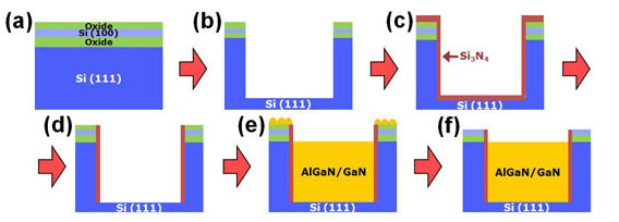
Epitaxial Stack Engineering
- AlN Nucleation Layer: Forms the interface with Si(111) and suppresses melt-back etching.
- Step-graded AlGaN Buffers: Gradually modify lattice spacing and stress through composition change.
- Superlattice Structures: Alternate thin AlGaN/GaN layers (5–20 nm periods) to dissipate stress and confine threading dislocations.
- Carbon or Iron Doping: Provides semi-insulating buffer for low leakage power HEMTs.
- GaN Channel / AlGaN Barrier: High mobility 2DEG region with tunable polarization charge and sheet density.
- In-situ SiN Cap: Passivates surface states and maintains mobility through barrier stability.
Silicon Substrate Preparation
Si(111) orientation provides the hexagonal symmetry alignment needed for wurtzite GaN nucleation. Prior to epitaxy, wafers undergo oxide removal, nitridation, and high-temperature surface conditioning. Low-defect epi growth depends on:
- Surface roughness < 0.5 nm RMS for uniform AlN wetting.
- Controlled bow and TTV for MOCVD wafer rotation stability.
- SiN or oxide edge coating to prevent Ga–Si melt-back at wafer periphery.
Defect Management & Reliability
Threading dislocation densities (TDD) in direct GaN-on-Si are typically 10⁸–10⁹ cm⁻²—higher than GaN-on-sapphire—but acceptable for lateral devices. Buffer and superlattice design significantly reduce dislocation propagation. Crack-free 200 mm wafers demonstrate long-term stability under thermal cycling and high field operation.
- Dislocation reduction: Achieved by inserting strain-compensating layers every 0.5–1 µm.
- Crack suppression: Buffer thickness control prevents tensile stress build-up at the interface.
- Leakage mitigation: Fe or C doping increases buffer resistivity to 10⁷–10⁹ Ω·cm.
Power and RF Applications
- RF HEMTs: Used in radar, 5G base stations, and satellite communication (S–Ku band).
- Power Devices: 600–1200 V e-mode/depletion-mode transistors for fast switching power supplies.
- LEDs & Lasers: Blue/UV light emission possible on Si for low-cost optoelectronics.

Device Reliability Considerations
Long-term device stability is governed by electric field distribution and interface trapping. Surface passivation and field-plate design reduce current collapse and improve dynamic RON. UniversityWafer wafers are compatible with standard PECVD SiN and ALD Al₂O₃ passivation schemes.
- Dynamic RON improvement: 40–60% reduction observed with optimized SiN thickness.
- Thermal management: GaN-on-Si’s higher thermal conductivity (vs sapphire) aids power cycling endurance.
- Interface stability: Pre-metal anneal recipes available for AlGaN barrier reliability.
Emerging Research Directions
Next-generation GaN-on-Si research explores vertical transistors, trench isolation, and hybrid integration with CMOS logic. 3D packaging and through-silicon vias (TSVs) now allow GaN power stages to coexist with silicon controllers on the same substrate, reducing parasitics and improving efficiency. UniversityWafer supports these efforts with thinned, metallized, and diced wafers ready for wafer-level packaging and power module integration.
Example Use Cases
- 200 mm GaN-on-Si templates for 650 V e-mode HEMT development.
- 150 mm superlattice buffers for radar and RF front-end transistors.
- Custom epi runs with integrated SiN caps for low-leakage sensors.
- Collaborative projects involving SiC–GaN hybrid wafer bonding.