Researcher question:
I need the effective density of states near the valence-band maximum and conduction-band minimum for n-type, p-type, and intrinsic silicon wafers. Could you provide this information?
The conduction band and valence band determine how electrons and holes move through semiconductor materials. Understanding the effective density of states, band gap, carrier concentration, Fermi level, and the behavior of n-type silicon, p-type silicon, and intrinsic silicon wafers is essential for semiconductor device design, electrical characterization, and materials research. This page explains the relationship between silicon energy bands, density of states, doping, conductivity, and carrier transport.

The effective density of states describes the number of available electron states near the conduction-band minimum or hole states near the valence-band maximum. These values are important when calculating carrier concentration, intrinsic semiconductor behavior, Fermi-level position, and the electrical properties of silicon wafers.
A PhD candidate requested information about the effective density of states for n-type silicon, p-type silicon, and intrinsic silicon wafers.
Researcher question:
I need the effective density of states near the valence-band maximum and conduction-band minimum for n-type, p-type, and intrinsic silicon wafers. Could you provide this information?
For crystalline silicon at approximately 300 K, the commonly used effective density-of-states values are:
NC represents the effective number of available electron states near the conduction-band minimum, while NV represents the effective number of available hole states near the valence-band maximum.
These parameters depend primarily on carrier effective mass and temperature. They are material properties and are not determined directly by whether the wafer is n-type, p-type, or intrinsic. Doping changes the carrier concentration and Fermi-level position rather than fundamentally redefining NC or NV.
Under nondegenerate conditions, electron and hole concentrations may be estimated using:
n = NC exp[−(EC − EF)/kT]
p = NV exp[−(EF − EV)/kT]
Where:
For intrinsic silicon, the electron and hole concentrations are equal. The intrinsic carrier concentration can be estimated from NC, NV, and the silicon band-gap energy.
The commonly used approximation is:
ni = √(NCNV) exp(−Eg/2kT)
Because the density of states varies with temperature, calculations performed significantly above or below room temperature should use temperature-adjusted values.
Reference #250233 for additional information, wafer specifications, and pricing.
UniversityWafer supplies intrinsic, n-type, and p-type silicon wafers for semiconductor physics, carrier-concentration studies, electrical characterization, device fabrication, thin-film deposition, and university research.
For the fastest quotation, include:
Get Your Silicon Wafer Quote FAST! Or, Buy Online and Start Researching Today!
There is no single dopant that automatically produces the highest conductivity in every n-type silicon wafer. Electrical conductivity depends on several connected factors:
For n-type silicon, the most common donor dopants are phosphorus, arsenic, and antimony. Heavily doped wafers generally have lower resistivity and higher conductivity, but very high dopant concentrations can reduce carrier mobility because of ionized-impurity scattering.
Phosphorus-doped silicon is widely used because it provides a practical balance of conductivity, dopant activation, availability, and process compatibility. It is common in integrated circuits, solar cells, sensors, MEMS, and general semiconductor research.
Arsenic-doped silicon can provide highly conductive n-type material and is frequently selected when a relatively shallow and stable donor profile is required. Arsenic diffuses more slowly in silicon than phosphorus, which can help preserve abrupt junction profiles during thermal processing.
Common applications include:
Antimony-doped silicon is valued for its low diffusion coefficient. It may be selected when maintaining a stable dopant distribution during high-temperature processing is more important than maximizing dopant solubility.
Potential applications include:
Conductivity should be evaluated from measured resistivity, carrier concentration, and mobility rather than from dopant identity alone. The relationship is commonly written as:
σ = q(nμn + pμp)
For a strongly n-type wafer, electron conduction dominates, so the expression is often approximated as:
σ ≈ qnμn
A four-point probe can be used to measure sheet resistance or resistivity while minimizing the effect of contact resistance.
The best wafer should therefore be chosen by specifying the required resistivity, carrier concentration, dopant, thermal budget, crystal orientation, and device process—not by assuming one dopant is always the most conductive.
Reference #270670 for n-type silicon wafer specifications and pricing.
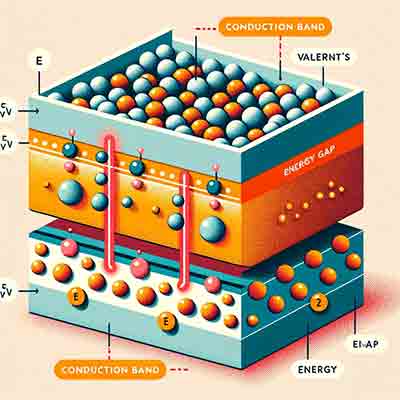 The conduction band and valence band are the two most important energy bands in semiconductor physics. Together with the band gap, they determine whether a material behaves as a conductor, semiconductor, or insulator. Understanding these energy bands is essential when designing transistors, diodes, solar cells, LEDs, photodetectors, integrated circuits, and other semiconductor devices.
In a semiconductor crystal, electrons normally occupy the valence band, where they participate in chemical bonding. When sufficient energy is supplied through heat, light, or an electric field, some electrons move into the conduction band, leaving behind positively charged holes. These electrons and holes become the charge carriers responsible for electrical conductivity.
| Valence Band | Conduction Band |
|---|---|
| Normally filled with electrons. | Contains free electrons capable of conducting electricity. |
| Electrons participate in covalent bonding. | Electrons move freely through the crystal lattice. |
| Lower energy state. | Higher energy state. |
| Produces holes when electrons leave. | Produces electrical current when occupied. |
| Dominates insulating behavior. | Determines electrical conductivity. |
The band gap (Eg) is the energy difference between the top of the valence band and the bottom of the conduction band. Electrons must gain at least this amount of energy before they can move into the conduction band.
Materials are generally classified as:
The valence band determines how atoms bond together and how holes are generated. Hole transport is fundamental to p-type semiconductors, CMOS technology, bipolar transistors, photovoltaic devices, and many optoelectronic applications.
Electrons promoted into the conduction band become highly mobile and carry current through the semiconductor. Device performance depends heavily on how easily electrons can reach and move within this energy band.
When an electron absorbs sufficient energy, it leaves the valence band and enters the conduction band. This creates an electron-hole pair, one of the fundamental mechanisms behind semiconductor operation.
Electron-hole pairs are generated by:
Their generation and recombination determine the performance of solar cells, LEDs, photodiodes, CMOS image sensors, and radiation detectors.
Doping changes the position of the Fermi level and increases the number of available charge carriers.
| Material | Dopant | Effect |
|---|---|---|
| Intrinsic Silicon | None | Equal electron and hole concentrations |
| N-Type Silicon | Phosphorus, Arsenic, Antimony | Additional electrons populate the conduction band |
| P-Type Silicon | Boron, Gallium | Additional holes are created in the valence band |
The Fermi level represents the probability that an energy state is occupied by an electron. In intrinsic silicon it lies near the middle of the band gap. Doping shifts the Fermi level toward the conduction band for n-type materials or toward the valence band for p-type materials.